Copyright © 1998-02-18 Charles Poynton
This paper explores how the temporal characteristics of image capture and image display devices interact with eye tracking.
A display system with a large pixel count can be exploited only by having a wide viewing angle, such as the 30 degrees of HDTV. Eye tracking - which is insignificant for conventional television - becomes significant in HDTV. A fast-moving element might take as little as two seconds to traverse the width of a screen; for 1920 samples per picture width, this corresponds to 16 pixels per field time at 60 Hz. Artifacts due to temporal effects at the camera, and artifacts due to temporal effects at the display, can be expected to be revealed in HDTV displays.
Many emerging displays have pixels that emit a constant amount of light throughout a large fraction of the frame time - they have long duty cycles. We have little experience of motion portrayal on displays having long duty cycles. Computers cannot yet display full-screen motion, and although conventional television can display smooth motion, it is restricted to narrow viewing angles. But it's clear that wide-angle, long duty cycle displays will introduce substantial blur on objects that the eye is tracking, and thus will have poor motion portrayal.
Many emerging display technologies, such as plasma display panels (PDPs) and digital-micromirror devices (DMDs) are intrinsically bilevel: At any instant in time, light is either emitted or not at any pixel. Apparent grayscale reproduction can be achieved by pulse-width modulation (PWM). The PWM technique works well when image content is static. But when PWM is combined with eye tracking in scenes with rapid motion, a new class of artifacts is introduced.
Digital technologists have long speculated about displays where each pixel is updated independently. It is assumed that if updating is at least as frequent as the arrival of new frames, the display will be free of artifacts. I will prove using several very simple examples that artifacts will be introduced unless the updating process is spatially coherent.
![]() You are reading
the HTML version of the paper. If you would like to read or print the typeset
version of this paper, I encourage you to access the Acrobat
PDF format (290353 bytes) of this note. You can find information
about document formats.
You are reading
the HTML version of the paper. If you would like to read or print the typeset
version of this paper, I encourage you to access the Acrobat
PDF format (290353 bytes) of this note. You can find information
about document formats.
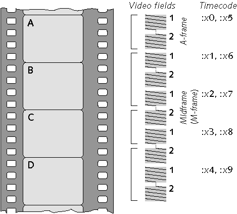
I will introduce motion portrayal by analysing the 3-2 pulldown process used to scan film, at 24 frames per second, to video at 60 fields per second. Figure 1 sketches four film frames; beside the set of film frames is the sequence of video fields produced by 3-2 pulldown. The O and E labels at the right indicate odd and even fields in an interlaced system. The first film frame is transferred to three video fields; the second film frame is transferred to two video fields.

The left graph of Figure 2 shows the vertical-temporal ( v - t ) relationships of 3-2 pulldown. The horizontal axis represents time; the vertical axis represents the vertical dimension of scanning. Dashed lines represent film sampling; solid lines represent video sampling. In film, the entire picture is sampled at the same instant. The staggered sequence introduced by 3-2 pulldown is responsible for the irregular spacing of the film sample lines. In video, using a tube camera, sampling is delayed as the scan proceeds down the field; this is reflected in the slant of the scan lines in the v - t axis.
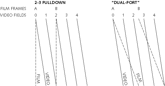
If you are a digital technologist, you might think that conversion from the 24 Hz film frame rate to any other rate could be accomplished by writing successive film lines into a dual port framebuffer at film scan rate, then reading successive lines out of the buffer at video scan rate. But if a scene element is in motion with respect to the camera, this technique won't work. The right portion of the v - t sampling graph indicates lines scanned from film being written into a framebuffer. The slanted dashed lines intersects the video scanning; at the vertical coordinate where the lines intersect, the resulting picture switches abruptly from one field frame to another. This results in output fields that contain spatial discontinuities.
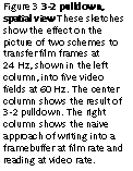
Figure 3 shows the effect in the spatial domain. Two intact film frames are shown at the left. The 3-2 pulldown technique introduces temporal irregularity into the video sequence, shown in the center column of five video fields, but the individual images are still intact. The result of the naive framebuffer approach is shown the right column: Spatial discontinuities are introduced into two of the five fields. With conversion from 24 Hz to 60 Hz, depending on the phase alignment of film and video, either two or three discontinuities will be evident to the viewer. With conversion from film at exactly 24 Hz to video at 59.94 Hz, the discontinuities will drift slowly down the screen.
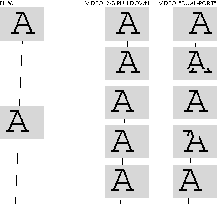
Using a pair of buffers - double buffering - and synchronizing the writing and reading of the buffers with the start of the film and video frames, keeps each frame intact and removes the spatial discontinuities. However, the delays involved in this technique reintroduce exactly the same temporal stutter as 3-2 pulldown !
Now I turn from the two dimensions of vertical displacement and time to the two dimensions of horizontal displacement and time. Figure 4 in the margin illustrates a cinema marquée with flashing light bulbs. At any moment two adjacent bulbs are on and the next three are off. The position shifts every tenth of a second, so that the cycle of five positions advances at one cycle per half a second. You look at the lights, and the pattern of dashes seems to move smoothly.
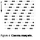
Imagine what happens if a shift pulse is omitted every three seconds. The pattern would appear to stutter; the motion would no longer be smooth. In viewing the marquée, your eye tracks the moving pattern in a smooth motion: Your eye does not dwell at one point then make a sudden jump every tenth of a second, but tracks the average angular velocity, in this case ten columns per second. The number of degrees per second depends on your distance from the display - the closer you are to the display, the higher its apparent angular velocity.
Now I will extend the cinema marquée example into a two-dimensional spatial example. The sketch below shows a sign formed from light emitting diode (LED) lamps. Static text appears like this:

In a display like this, each LED does not have its own individual drive circuit. Instead, the LEDs in are wired in a matrix; only one row can be activated at a time. The LEDs in the bottom row that are necessary to form a message are lit first, for a short period of time. Then the necessary LEDs in the penultimate row are lit. Each row up the height of the display is lit in turn, ending with the top row. The display scanning is comparable to a CRT whose phosphor persistence is about a line time, except that scanning is from bottom to top instead of top to bottom.
Consider what happens if the pattern that forms the message is shifted one column to the left in each successive scan. As in the cinema marquée, your eye tracks the average velocity of the moving pattern. If the height of this display is scanned 70 times per second, and there are seven rows, the apparent velocity will be ten columns per second.
When the bottom row is lit, it forms an image on your retina. At the instant the row above is lit, your eye's gaze point has advanced 1 / 7 of the way toward the next column to the left. Each successive row illuminates a position on your retina that is displaced towards the next row. By the time the bottom row illuminates again, your gaze point has shifted by exactly one column.
The effect of scanning combined with eye tracking is that the message on the display appears slanted. In this example the angle is tan-1 ( 1 / 7 ), or about 8 degrees. The apparent image looks like this:

Western languages are read from left to right, so to follow reading order, the message must be scrolled in from right to left. The handwriting of a right-handed person - or the derivative of handwriting, italic type - is slanted with the tops toward the right. The developers of scrolling LED signs simulate italics by scanning from bottom to top. If the display were scanned from top to bottom, the slant would be to the left.
In this example, the interaction of scanning and eye tracking has introduced a spatial artifact - a slant - into the image. The image in this case is a trite one. The example in Figure 3 is similar, in that a scanning effect introduced spatial artifacts into the picture.
Sharing the row and column wiring of the LEDs - display multiplexing - is an economic necessity. But at any instant in time all but one row of the display are extinguished; this limits the brightness of the display. The column wiring of the display can be split at the center, so that the top half of the display is accessed from wires at the top, and the bottom half is accessed from wires at the bottom. Twice as many row driver circuits are required, but this scheme allows two rows to be illuminated at once, doubling the display's intensity.
But consider how the split wiring scheme affects the apparent image if it is in eye-tracked motion. If the top and bottom halves of the display are each scanned from bottom to top, here is the result:

If the top of the display is scanned from the middle to the top, and the bottom half is scanned from middle to the bottom, the scrolling message looks like this:

In Figures 5 through 8, I used the example of a scrolling LED sign, but the example is directly applicable to liquid crystal display (LCD) panels. Many of these panels are not only split top to bottom like Figure 6, but also split side to side, so as to form four quadrants. If an image element has the misfortune of moving across or along the joint between quadrants, it will suffer the same fate as Joe in Figure 7.
Digital technologists have speculated about displays where each pixel is updated independently. It is assumed that if updating is at least as frequent as the arrival of new frames, the display will be free of artifacts. But if a moving element is being eye tracked at ten pixels per frame, and its pixels are being updated at random instants throughout the frame time, the pixels will appear to be displaced random amounts between zero and ten pixels. If the moving element contains detail on a scale in the order of a few pixels, large amounts of noise will be introduced. If the pixels of a display are updated systematically, but in a manner incoherent with the frame rate of the images, then large scale spatial artifacts, such as that of Figure 3, will be introduced.
There is stutter when only 24 frames of information are available to fill 30 slots. If 24 Hz film were presented using 1-1-1-2 pulldown on a display that operated at 30 Hz, the stutter - six times per second - would be pronounced: the display sequence would start frame 1, frame 2, frame 3, frame 4, and frame 4 repeated; then 5, 6, 7, 8, 8 repeated, 9, 10, 11, 12, 12 repeated, and so on. The visibility of stutter peaks between 2 and 10 Hz. For 3-2 pulldown from 24 Hz to 60 Hz, the stutter is twelve per second, which is significant but high enough not to be objectionable.
If the display rate were raised to 69 Hz, the stutter rate would drop to three per second. This would be quite unwatchable. In these examples, where the display rate is much higher than the source frame rate, the stutter rate is a function of the smallest difference, or beat frequency , between any multiple of the film frame rate and the display rate.
Practical image capture devices do not capture instantaneous snapshots of the scene in front of the lens. Instead, light from the scene is integrated for a period of time that depends on the physics of the device, and possibly also on settings made by the cameraperson.
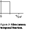
A film camera normally exposes 24 frames per second, but the exposure time of each frame is considerably shorter than 1 / 24 s. A film camera normally closes its shutter for half the frame time. This period of time is required for the camera's film transport to physically advance the film. Since the shutter is usually implemented as a rotary mechanism that makes one revolution per frame, the duration of the exposure is usually expressed in an angle in degrees. Film is normally exposed with a 180° shutter angle, but some cameras can expose as much as 200°, and a cinematographer may shorten the exposure. Figure 9 in shows the temporal sampling function of a film camera.
A noninterlaced video camera using a tube-type pickup, such as a vidicon, integrates for a frame time. This is illustrated in Figure 10 in the margin. The integration introduces blur to scene elements that are in motion with respect to the camera, as I will describe.

A video camera with a CCD as its photosensor may integrate for as long as a frame time, but contemporary CCDs have electronic shutters that permit the cameraperson to select a shorter exposure interval. For the remainder of this discussion I will assume that the CCD has been shuttered down to a small fraction of the frame time, say an exposure of 1 / 1000 second. Figure 11 in the margin is a sketch of the temporal sampling function of a CCD set for a short exposure time.

A film camera captures 24 frames per second, but even in the dark viewing environment of a cinema theater that rate is insufficient to overcome flicker. If the rate is doubled to 48 Hz, flicker is largely overcome. But it is not necessary to display 48 unique image frames per second: reasonably good motion portrayal is obtained with 24 frames per second, flashing each frame twice. The temporal response of a typical film projector is shown in Figure 12 in the margin.

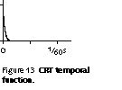
CRT displays used for video have
very short persistence. For a typical phosphor, it takes on the order of
50 ![]() s for intensity to fall to
1 / e, about 37%
of its peak. Each pixel is displayed as a very brief, very bright flash.
The apparently constant illumination on the display surface is a consequence
of the properties of vision, not of the CRT. The rapid exponential decline
is sketched in Figure 13 in the
margin.
s for intensity to fall to
1 / e, about 37%
of its peak. Each pixel is displayed as a very brief, very bright flash.
The apparently constant illumination on the display surface is a consequence
of the properties of vision, not of the CRT. The rapid exponential decline
is sketched in Figure 13 in the
margin.
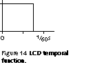
A liquid crystal display (LCD) has a constant backlight, and an array of light valves. In this discussion I will describe a grayscale LCD, where light transmission through each pixel is controlled in an analog fashion. Each pixel is transparent to a controlled extent for the majority of the frame time, but the physics of the device demand that over some fraction of the frame time - perhaps 25% - the pixel is opaque. Figure 14 sketches the temporal function of an LCD with a 75% duty cycle.
Certain kinds of LCD panels - and many emerging display technologies such as plasma display panels (PDPs) and deformable-mirror displays (DMDs) - are intrinsically bilevel: At any instant in time, light is either emitted or not at any pixel. Apparent grayscale reproduction in these displays is achieved by pulse-width modulation (PWM): A bright pixel is lit for a large fraction of the frame time; a dim element is lit for a small fraction. When a foreground element in motion is eye-tracked on a pulse width modulated display, the width of the blur depends on the intensity of the element.
I have described how the temporal characteristics of a capture device affect the recorded image, and I have described temporal properties of common displays. The capture characteristics are recorded in the media; obviously, they are independent of viewing. When you view the media with a stationary gaze, you perceive the image exactly as recorded. But when your gaze tracks an element that is in motion with respect to the display, capture and display characteristics interact. I will explain these interactions using a test scene. I will explain the effects in terms of a noninterlaced video system, but the effects are identical with interlace.
Figure 15 shows the test scene. The light gray circle in the upper half of the scene is stationary with respect to the camera. The tall white rectangle in the lower half is in motion to the right with respect to the camera; during the frame interval, it moves by the amount indicated by the arrow. The calibration line underneath is shows its displacement.

Most contemporary CCD cameras can be set for a short exposure time. Figure 16 shows the test scene imaged by a CCD with a short exposure, say 1 / 1000 s. The rectangle exhibits no blurring. A CCD can be set to integrate for a period of time up to the frame time, resulting in a situation like that of the vidicon example that I will describe in a moment.

Figure 17 shows how the scene is imaged by a film camera with a shutter angle of 135°. The shutter remains open while the rectangle traverses a certain distance across the field of view, so the rectangle blurs in its direction of motion.

A vidicon integrates the scene
for the whole frame time; think of a shutter being open for that period
of time. Figure 18 shows that
the blur seen by the video camera is greater than that of the film camera.

The capture examples show the dependence of the recorded image on the temporal sampling characteristics of the capture device. Upon display, if your gaze is stationary with respect to the display device - if your gaze is fixed on the circle, for example - the reproduced image will be the same as the sketches above. But upon viewing this scene, it is likely that your gaze will follow the rectangle - you will engage in eye tracking . Two interesting studies of eye tracking in television have been published by Fukuda and Yamada, of NHK Laboratories.
If your gaze is tracking the rectangle, then obviously the blur introduced by the camera will contribute to your perception of the image. But, not so obviously, the temporal characteristics of the display device will also influence the apparent image. In the following sequence, I will use examples of the test image from the capture devices above, displayed on each of three displays: a film projector, a CRT, and an LCD with 75% duty cycle.
For the moment, disregard the stationary circle. I have cropped the circle out of the next few pictures; I will reintroduce it in a moment.
Figure 19 shows the bottom portion of the test scene, as captured on film and viewed on a two-bladed film projector, when your gaze is tracking the rectangle. The rectangle appears somewhat more blurred than the image of the rectangle recorded on the media: The projector's shutter is open for a considerable time while your gaze point is tracking across the screen, so the image blurs on your retina. But more significantly, an apparent double image forms: When the shutter opens a second time on the same frame, your gaze point has advanced half way to the position of the rectangle at the next frame: the rectangle is imaged onto your retina a second time, but in a different position.

A CRT has a very short flash: the persistence of the phosphor is a negligible fraction of the frame time. So when a moving element is tracked on a CRT display, its image on the media is effectively "flashed" once per frame time onto the retina; the flash of each frame occurs just as your gaze point arrives at the next position of the rectangle. So a CRT introduces no additional blurring. However, a short flash time has a disadvantage that I will explain in the next section. Figure 20 shows the test scene as imaged on a CCD and viewed on a CRT.

The sketch in Figure 21 shows the test scene as viewed on an LCD with a duty cycle of 75%. A considerable amount of blurring is introduced to the CCD's image which is, on its own, free from blur.

Figure 22 shows the test scene as imaged on a vidicon, viewed on a CRT. The image from the vidicon is already severely blurred; the CRT introduces no additional blur.
![]()
A moving element that is eye tracked on the display is subject to blur, and as you see from the CRT examples, this blur is minimized by a short flash time at the display: But the advantage of a short flash time for motion is accompanied by a detriment to stationary elements on the display. I have cropped the stationary circle out of these examples, but now I will reintroduce the circle and explain the effect.
Figure 23 shows the test scene imaged by a film camera and displayed on a film projector. The eye tracked rectangle doubles-up, as I have mentioned. Here I have reintroduced the stationary circle. As you track the rectangle while the projector flashes, the circle is flashed onto different positions on the retina: the circle will strobe . The camera usually tracks the motion of a foreground element in the scene; in this case, the rectangle is the foreground and the circle is the background. So the effect is usually called background strobing .

If, as in this example, the background comprises a single, small element, it will be mapped onto the retina in a periodic spatial pattern. But each element will be flashed only once, and because the projector's shutter is open for a fairly long fraction of the frame time - a total of 50% - the strobing background will be blurred, thus not too objectionable. If the background has periodic spatial content of its own, unfortunate situations can arise where the pitch of the background pattern matches the pitch of strobing due to a foreground element being eye-tracked at the display. This can cause highly objectionable artifacts.
Figure 24 shows the rectangle captured without blur by the CCD, being eye tracked and reproduced without blur by a CRT. Due to the brief flash of the CRT, the background circle now flashes very sharp circles onto the retina, once per frame, as the foreground is tracked. A strobed background is inevitably as sharp as an eye-tracked foreground element. In this case, background strobing is quite severe.

Although blur in an eye-tracked foreground is a function of the temporal characteristics of both the capture and display devices, background strobing is a function solely of the display. Figure 25 illustrates that even a the blurred image from a vidicon is not immune from background strobing when displayed on a CRT.

To give you an idea of the magnitude of these effects, consider that conventional television is ordinarily viewed from a distance of about seven times the picture height: The display occupies a horizontal angle of about ten degrees. A very fast-moving element might take a second to traverse the width of the screen; for 640 samples per picture width, this corresponds to about ten pixels per field time at 60 Hz. In 1125/60 high definition television (HDTV) there are about 1920 samples across the width of the picture: An object that traverses the width of the screen in one second moves 25 pixels per field time. The motion estimation and interpolation machinery of MPEG-2 accommodates horizontal motion of 32 pixels per field time.
A CRT display is the worst case for the introduction of background strobing. But strobing has not been a serious problem for television, because conventional television has such a narrow viewing angle that eye tracking is minimal. As viewing angles increase with the introduction of high definition television (HDTV), eye tracking will increase, so we can expect the incidence of strobing artifacts to increase.
In cinema, one of the functions of the cinematographer is to prevent excessive background strobing. He or she does this by controlling the speed of moving foreground elements with respect to the camera, and by controlling the visual content of the background. Background strobing only occurs when a foreground element is being eye tracked. If the cinematographer can make a good guess, based on the nature of the scene, on what elements the viewer will track, this will help to minimize the visibility of strobing artifacts.
I have discussed eye tracking in terms of the displacement of the gaze point in the image. But we can turn this around and recast the explanation from the viewpoint of the retina: When eye-tracking, pixels of the display system traverse the retina. If the eye is tracking at a rate of ten pixels per frame time, then each pixel on the display traverses a swath ten pixels long across the retina during each frame interval. Considered from this point of view, effects of pixel duty cycle, asynchronous pixel updates, and other temporal effects are fairly easy to visualize.
For objects in motion with respect to a video or film camera, there is an inherent trade-off between a long exposure time, which will cause blurring of moving elements that the viewer is eye tracking, and a short exposure time, which will cause strobing of moving elements that the viewer is not tracking. Anecdotal evidence suggests that an exposure time of 1 / 3 of the frame rate is a good compromise.
In image capture, exposure time may be fixed by the physics of the camera. But if the camera allows a choice, exposure time should be chosen depending on scene content, and depending on what elements in the scene are likely to be eye-tracked by the viewer.
A display having a long duty cycle - an LCD, for example - is bound to introduce excessive blur when a fast-moving object is eye-tracked. For display of objects in fast motion with respect to the display, the shorter the duty cycle the better. The relatively long integration of tube cameras, and the short persistence of CRT displays, makes a surprisingly good combination. But a short duty cycle at the display will introduce strobing into background elements.
A displays that achieves grayscale through pulse width modulation is liable to introduce spatial artifacts when eye-tracked. High spatial frequency artifacts are less objectionable than low spatial frequency artifacts. The PWM modulation scheme will have an effect on the visibility of artifacts.
As we design and deploy video capture and display devices, we should consider how their temporal characteristics interact with eye tracking.
Find an analog video switcher. Select a horizontal wipe - the transition whose feature at 50% of the transition is a vertical line. Select a white flatfield on one input and a black flatfield on the other. Perform rapid wipes, repeatedly, back and forth. Does the edge appear slanted? Which way?

Find a digital video switcher, and perform the same exercise. Does the edge appear slanted? Which way?
Copyright © 1998-02-18 Charles Poynton